Roof reconstruction Hangar 3 at Munich Airport
26 April 2022 , MEFA blog team
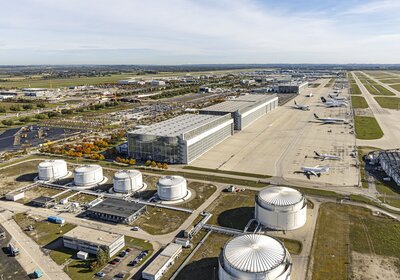
Aerial view of maintenance hangar 4 (front) and maintenance hangar 3 (back), which is about twice as large, at Munich Airport.
Image: Michael Fritz for Munich Airport
Heavy rainfall events pose ever greater challenges to buildings, industrial plants and entire cities. In addition to the generally known cases of damage, the masses of water also pose a problem for flat roofs: These have an upstand (parapet) at the edge so that the waterproofing of roofs can be connected, and superstructural parts remain invisible from the ground. During heavy rainfall, drainage via the canalization often reaches its limits and the water level on the roof rises quickly. In extreme cases, this can even lead to overloading of the roof construction.
For this reason, DIN 1986-100 requires, in addition to conventional drainage into the canalization, an additional emergency drainage system that drains the roof in a free jet onto the property. "The design basis for an emergency drainage system is the 5-minute century rain, for which there are table values. Such events are localized, and the rainfall amounts also vary greatly from region to region," reports architect Arne Zucker of GFM Bau- und Umweltingenieure in Munich, who planned the roof reconstruction for Hangar 3 at Munich Airport. The rain of the century is characterized by the amount of rain that can statistically be expected once every 100 years.
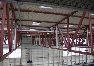
Roof construction of the hall - view from the south to the closed north wall of the hall. The pipeline routes for the emergency drainage had to be inserted in such a way that the operation of crane runways was still possible, and the overhead clearance was not restricted.
Image: Saint-Gobain
Standard requires additional emergency drainage
"When Hangar 3 was built 30 years ago, emergency drainage was not yet in the standard," Zucker continues, "but since then, heavy rain events have increased. Even if nothing has happened at Hangar 3 so far, at the latest when a building measure is pending, in this case the due roof reconstruction, the building must be brought up to the status quo with emergency drainage in accordance with the standard." To give a sense of the numbers, Zucker gives dimensions for Munich Airport. Accordingly, the 5-year, 5-minute rainfall event delivers a rainfall donation of 250 liters per second per hectare. In contrast, the 5-minute century rain event delivers 775 liters per second per hectare. The 5-year rainfall is the design basis for regular drainage. On the other hand, the emergency drainage system should be able to handle the 100-year 5-minute rain on its own, since the regular drainage system at the canal could also become clogged at some point and may not be able to drain freely.
At Hangar 3, the existing regular drainage to the canalization could remain in place. For larger rain events, a pressure stream drainage system was selected. In this mode of operation, the pipelines fill completely with water, which is achieved via a cross-section constriction near the end of the pipeline. The geodetic difference in elevation then provides velocities of flow that are substantially higher than the velocities of gravity drainage, in which the pipelines are only partially filled with water. Advantages of pressure stream are smaller pipe dimensions, self-cleaning due to high flow velocities, laying without a down-grade and, as a result, flat slope constructions below the ceiling.
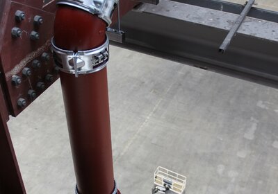
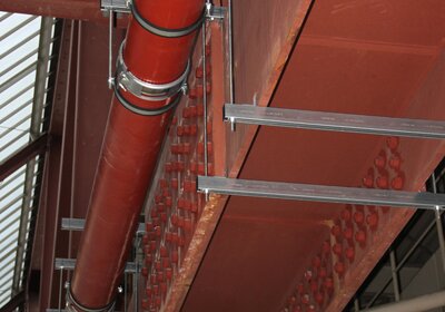
When the water flow is diverted, here by 90° with a height offset, high forces occur that must be calculated and absorbed by the design of the pipeline fixings.
Image: Saint-Gobain
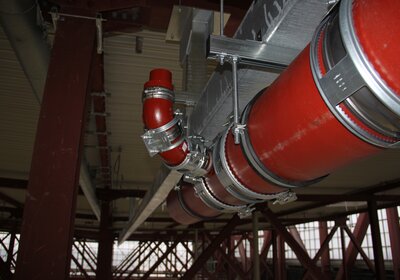
A branch pipe of the emergency drainage system, into which the water masses are coupled from a roof drain. Further back, the connecting pieces for other drains of the emergency drainage system can also be seen under the roof.
Photo: Frank Behnisch, Manfred Himmelreich & Co. GmbH
Cast iron was chosen as the material for the drainage pipes. Compared to plastics, cast iron has a higher strength and a significantly lower thermal linear expansion. In addition, according to the fire protection concept, combustible building materials were to be avoided as far as possible.
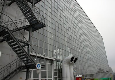
The hall in the southwest of the Munich airport site has a width of 305 m and is oriented east-west. It is divided in two approximately in the middle by a fire protection wall. It is approximately 84 m deep and 32 m high. The division of the hall into two parts allows the roof to be reconstructed in sections. Flatter buildings adjoin to the north, and to the south towards the taxiway there is a somewhat lower porch with a depth of 5.5 m, into which the gates are built.
East facade of Hangar 3: With a total width of 305 m, a depth of 84 m and a height of 32 m, the building has imposing dimensions and is separated into two parts on the inside by a fire protection wall.
Image: Saint-Gobain
Emergency drainage only runs during large amounts of rainfall
According to the flat roof guideline, the slope must be 2%. The roof surface is designed in such a way that the water collects in two linear depressions running in an east-west direction. The drains of the old standard drainage system are also lined up there. At a distance of around 1 m from the low points of the depressions, and therefore slightly elevated, the drains for the emergency drainage system, 44 per half of the hall, are placed in the roof. These have a retaining ring so that the emergency drainage system is only activated when the water level reaches around 10 cm. It reaches its full capacity when it is flooded by another 5 cm, as Arne Zucker explains.
Five pipeline routes for emergency drainage were planned for each half of the hall, one of them for the southern porch. With the specification of the pipeline route, the cast iron pipe manufacturer Saint-Gobain was able to calculate the hydraulics and the required diameters - in this case up to 300 mm. This meant that weights and also forces for diverting the water flows were known for the design case. The next step was the design and construction of the pipe supports, for which GFM Bau- und Umweltingenieure called on MEFA's planning support. In addition, we of course supplied the components for the pipe mounting.
For each half of the hall, two emergency drainage outlets now lead to the outside. Since one half of the hall has an area of about one hectare, in the case of the 100-year rain event, a total of about 500 l/s distributed over two outlets will escape. That's quite a punch, and so conspicuous markings and warning signs were placed at the outlet points. Since even 50 liters per second and hectare are considered heavy rain, as Arne Zucker points out by way of comparison, hardly anyone is likely to voluntarily stay in the danger zone during the larger events.
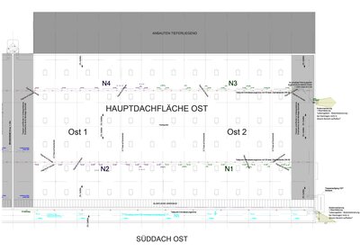
Plan of the eastern half of Hangar 3: The regular drainage is marked in red and the pipelines and outlets for the emergency drainage N1 to N5 in green, purple and light blue. The emergency drainage outlets are marked by conspicuous hatching.
Image: Munich Airport
About the planning in detail
Inserting the pipeline routes into the existing supporting structure was often a challenge in this project, because the existing structure could not always be used and so additional beams had to be attached in many cases. A total of around 1.3 km of cast iron pipe was installed on the ceiling structure at heights of up to 32 meters. The cast iron pipes have a standard length of 3 m and are usually attached at two points. For the pipes with a diameter of 300 mm, even a triple suspension was provided due to the high weights. The task of MEFA's planning support was the detailed planning and design of the pipe suspensions and, above all, the calculation of the fixpoints, because when the water masses are diverted under full load, high forces occur that have to be transferred from the pipe fixing to the supporting structure. A few numbers demonstrate the size of the project: A total of 60 fixpoints were required, profile rails with a total length of 1750 m were processed, plus 3550 m of threaded rods and 1100 pipe clamps.
For the pipeline route, the existing supporting structure was used wherever possible, of course. The picture from the area of the porch facing south shows how the installation works in practice without drilling into the steel beams.
Image: Saint-Gobain
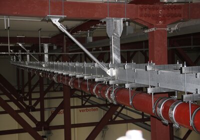
Often, however, the existing supporting structure could not be used for the pipeline route. Then additional beams had to be mounted. In the background on the right, the old drainage runs along the low points of the flat roof.
Photo: Frank Behnisch, Manfred Himmelreich & Co. GmbH
Another point is the compensation of thermal expansion. During seasonal changes, no problems occur because the steel structure of the roof and the cast iron pipes expand to a similar extent. In the event of heavy rainfall, the situation is different, because in summer the temperature under the roof can easily reach 50 °C. If a heavy thunderstorm then occurs, during which the water may have a temperature of 20 °C or less, considerable changes in the length of the pipelines will occur, given the dimensions of the hall. These must be compensated for by sliding elements in the pipe fixings and other construction measures.
Rational assembly due to prefabrication
The on-site assembly was carried out by the company Manfred Himmelreich & Co. GmbH in Munich. Managing Director Sebastian Beer: "I entrusted this demanding and not everyday project to my service engineer Frank Behnisch as site manager, a very experienced man who also always thinks about the most rational assembly possible, which is absolutely crucial for such projects alone because of the large masses that have to be processed."
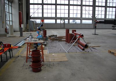
In cooperation between the GFM planning office and MEFA's planning support, the detailed plans and the stress analyses for the pipeline fixings were created. Behnisch then built samples for each fixing situation in a temporary workshop area on the hall floor. After testing and trial assembly, series production was then carried out. "In this way, we only had to hoist finished assemblies to a height of 30 m and mount them, which simplified the work considerably. Considering the dizzying heights, the advantage of prefabrication is quite obvious, but shop-based preassembly of repetitive assemblies is absolutely recommended in other ways as well. We always think in advance about how we can implement this in the most sensible way," says service engineer Frank Behnisch. After all, pre-assembly conserves the labor factor, which is becoming increasingly valuable today. The assembly of subassemblies, often in very confined spaces in shafts, in supply tunnels or, as here, at a height of 30 meters, is of course a considerable additional workload for the fitters. In addition, pre-assembly under workshop conditions saves valuable time on the construction site and provides planning reliability.
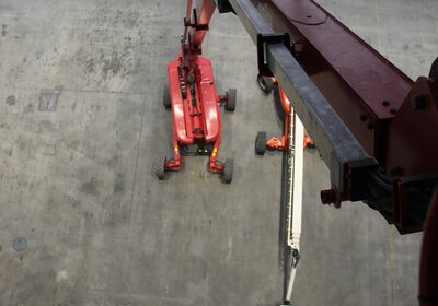
Assembly at a height of 30 m - the fitters from Himmelreich have to be free from giddiness. The south side with its sliding gates can be seen in the background.
Image: Saint-Gobain
Provisional workshop area of the plant construction company Manfred Himmelreich. This is where the prototypes for the fixing technology were built. After testing, these went into series production. The gates on the south side of the hangar can be seen in the background.
Image: Saint-Gobain
In this context, we also offer pre-assembly ex works. However, the Himmelreich company did not take advantage of this additional offer, after all, the conditions for preassembly in the aircraft hall were very favorable. At least, however, the assembly company purchased cut-to-size profile rails for preassembly of the assemblies on site. "For all of us, the construction of the emergency drainage system was a particularly exciting project due to the unusual challenges involved," concludes Frank Behnisch.
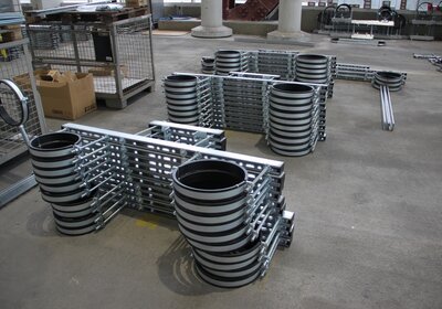
The prefabrication of assemblies for the pipeline suspension greatly facilitates the assembly process. In this project, the individual groups were manufactured in large quantities in the workshop area.
Image: Saint-Gobain
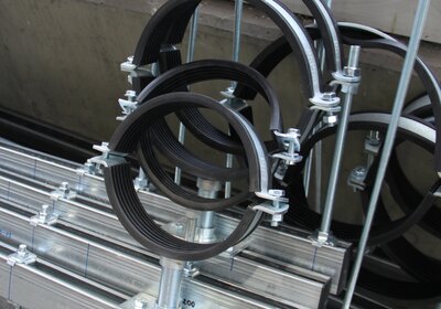
Bearing position for the prefabricated modules. Since beams in steel construction must not be drilled into for structural reasons, these fixings enable a connection by clamping. The distance angles prevent slipping to the side.
Image: Saint-Gobain
Strong support from suppliers
"And despite many parties involved in this project, the construction project went relatively smoothly and satisfactorily," as Arne Zucker summarizes. "The suppliers MEFA and Saint-Gobain always delivered their calculations and plans reliably in reasonable times, and whenever I had a question for the companies, I always received competent answers in a timely manner."

