Secure fixing to steel beams
01 February 2022 , Volker Weber, product manager
Pipeline installations in halls
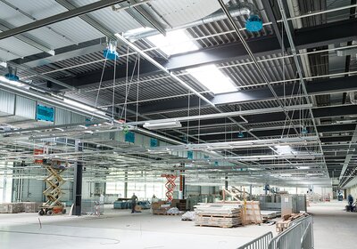
Industrial hall buildings should provide as much free space as possible for traffic areas and the assembly of machinery. The construction method with steel beams offers advantages here, as it allows large spans between supporting beams and hall walls. However, conventional options for fixing pipelines or cable routes are only available to a limited extent in such halls. Simple pipeline fixing and suspensions with threaded rods are possible in the trapezoidal or sheet metal ceiling that lies above the supporting steel construction, but they can only be subjected to low loads (clearly less than 1 kN) per anchorage point.
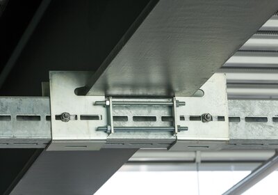
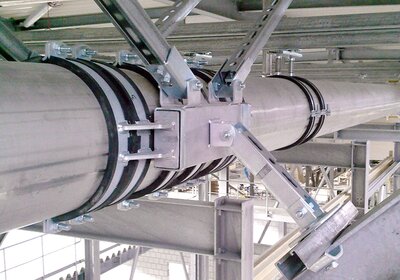
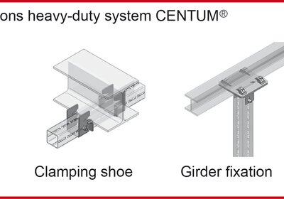
If drilling or welding is not allowed, clamping solutions for profile rails, such as the clamping shoe for the MEFA CENTUM® mounting system shown here, offer a way out.
For higher loads or complete rail constructions, usually only the flanges of the steel beams are available. However, at the latest when reaching for the drilling machine, the person responsible for industrial engineering will point out to the assembly personnel that drilling or welding on steel beam constructions is not permitted.
Fix pipes where drilling is not allowed
For pipeline installations in hall buildings, systems are available that use clamping solutions, profile rails, connecting parts and threaded rods to enable safe mounting in all imaginable situations. Planning and selection of fixing solutions are based on the following questions:
- How many pipelines are to be fixed and with which dimensions and weights?
- What type and size of steel beam profiles are available for fastening?
- Which distances between the possible fixing points have to be bridged?
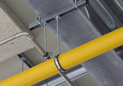
Example of fixing individual pipelines to beam profile with short rail piece and clamping bows on both sides.
The decisive factor is which additional loads are to be attached to the statically relevant steel beams. These must be checked and approved by the specialist responsible for the building statics. Pipe weights, the media to be transported, the intended insulation and the fixing material itself are included in the load determination. In addition, the fixing distances can be determined in advance on the basis of the smallest pipe dimension.
Clamping instead of plugging and screwing
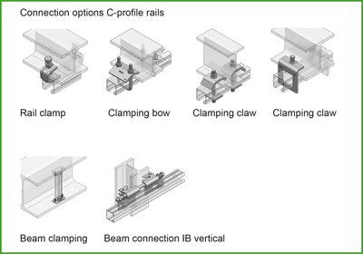
The basic principle for pipe fixing to steel beams is the clamping of specially designed fixing elements to the beam profile. The beam connection of profile rails, for example, is made with clamping bows consisting of a U-bolt and an angled clamping claw. For each beam connection, these clamping solutions are generally arranged on both sides of the beam. The connection on both sides prevents the clamping solution from loosening due to vibrations or thermally induced movements. At the same time, this reduces the deflection of the rails. In addition to the clamping bow described above, there are a number of other clamping options, such as claws or clamping claws.
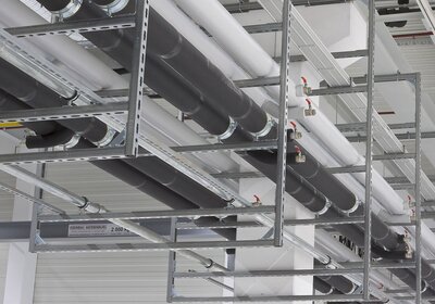
Frame structures with rail systems allow variable mounting of pipelines, which can be easily extended or changed later.
The most common and at the same time most flexible connection for individual pipelines is made on profile rails, which are mounted below the steel beam. Here, the rails can either only run across the width of the beam or also project out a little, in which case the lever arm and the incoming torques can lead to a more solid profile rail. In most cases, the profile rails are fixed running transversely from steel beam to steel beam, or they can be fastened over several beams in the sense of a continuous beam. This fixing solution offers the advantage that the mounting of the pipe is not directly tied to the line of the beam.
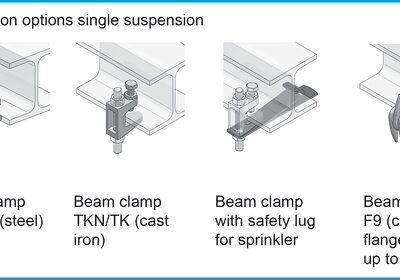
A single threaded rod for pipe suspension can also be fixed by means of beam clamps. However, certain requirements apply here. For example, most beam clamps are only suitable for steel beams with straight and non-inclined flanges. Beam clamps may only be loaded by vertical tension. They are also frequently used for sprinkler systems. According to VdS regulations, an additional safety lug must be provided for this purpose.
In the case of a larger number of pipelines, multi-level frame constructions with rail systems are suitable.
Pipeline routes with multiple pipelines
Standard mounting situations include the pipeline route with a certain number of pipelines with smaller cross-sections, which, including the pipe insulation, occupy a total width of up to about 1 m. Clamping profile rails to the underside of the beam creates the basis for simply inserting the individual pipe fixings into the C-profile of the rail using rail system accessories such as threaded and retaining plates. If there is a lack of the necessary width in hall buildings for laying pipeline routes in order to arrange all pipelines next to each other, it is possible to make use of the available height. Profile rail systems can be used to create frame structures consisting of vertical and horizontal rails, so-called multi-level rail frames, each of which can accommodate a certain number of pipes on two or more levels. Appropriate beam fixation are used for the vertical attachment of rails to horizontal beams.
Bridging of large spans
To bridge a span of, say, six meters between two beams, C-profile rails with a greater construction height should be used. Single or double rails are available for this purpose. A 45-60 single rail can be loaded with only 0.12 kN in the middle of the rail at a span of 6 meters, but the 45-120 double rail already offers a permissible load of 1.38 kN. Furthermore, heavy-duty profiles such as our CENTUM® XL 200 profile with a height of 200 mm, a width of 100 mm and a wall thickness of 5 mm can be loaded with 14.35 kN in the same application.
A ceiling grid system with continuous profile rails offers maximum flexibility for running of cables if the machinery to be supplied is to be change-friendly.
Another application is to insert the rails between the beam flanges. This fixing variant requires a straight (not inclined) beam flange. In this case, the ends of the rail rest on the lower beam flange and are secured with a simple clamping bow - in addition to convenient insertion mounting, this application also offers very large supporting forces, but the rails must be cut exactly to size.
Mounting on vertical beam profiles
If the media supply is required at a height of 4 m in an 18 m high hall, only the vertical beam supports may be available for fixing the line route. In this mounting situation, there is a risk of slipping even with smaller vertical forces when profile rails are fixed with clamping bows or clamping claws. Special problem solvers are available for this situation, such as our beam connection IB vertical: This system consists of two clamping claws with a V-shaped cut, which are connected by a threaded rod. Due to the V-shape, it pulls the claws into the beam flanges when the threaded rod is tightened. In compliance with the tightening torques, this allows loads of up to 4 kN in the vertical direction.
For aggressive environments, support constructions and fixings are also available with TSP protection system, which meets the requirements for corrosion-protection class C3 to C5.
Variable fixings in the grid field
Depending on the use of hall buildings, it may be necessary to create as close a network of fixing opportunities as possible. One example is production halls, where the locations of machines and equipment change more frequently. With a ceiling grid system, the media and connection pipes can be quickly and flexibly adapted to changing situations. To bridge large spans, elements for connecting rails in the longitudinal direction are available within the profile rail ranges. These should be arranged in the area of small bending moments - for example, near a beam connection or at a point of low load. Tension rod systems or additional bracings can also be fitted as a supporting measure.
Fixpoints for linear expansion
Pipelines in hall buildings often run over long distances. Flow media with changing or high temperatures cause linear expansions. Fixpoints are required to control these expansions in a controlled manner and to specify their direction. The complete pipe run must be known in order to place the fixpoints correctly. Fixpoints may also be necessary in the event of water hammer generated by valves, flaps or pumps.
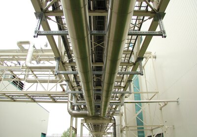
With the connecting elements belonging to the rail range, even complex constructions such as this fixpoint fastening can be realized.
Profile rail systems, with the associated connecting and tensioning elements, also enable the production of fixpoints on steel beams. For the application area of fixpoints, we offer project-specific special solutions that can be planned and built by the in-house application engineers and production in cooperation with the executing companies.
Conclusion
For the installation of pipelines in steel construction halls, fixing systems are available which, with clamping solutions, profile rails, connecting parts and threaded rods, enable safe mounting without drilling or welding. Precise planning is highly recommended in advance, especially since the loads for the beam constructions must be approved by a structural engineer. Since experience shows that there are requests for changes during the construction phase and afterwards, planners and executing companies are well advised to choose a supplier with a comprehensive and coordinated product range as well as high-performance support.
Writer
Volker Weber, product manager
Overview of the various options for connecting profile rails to steel beams. This means that safe pipe installation is no longer a problem for steel construction halls.

